Middle-Column Gap Balancing and Middle-Column Mismatch in Spinal Reconstructive Surgery
PAUL C. McAFEE, MD, MBA, BRYAN CUNNINGHAM, PHD, KEN MULLINIX, MS, ELLIOTT DOBBS, BS, LUKAS EISERMAN, PHD
Spine and Scoliosis Center, University of Maryland St Joseph Medical Center, Towson, Maryland
ABSTRACT
Background: Middle-column gap balancing (MCGB) is a reference measurement of the path of the posterior longitudinal ligament (PLL), which is reconstructed under tension and balanced by the combined height of the posterior one-third of the vertebral bodies and the posterior one-third of the disks, including any intervening load-sharing spacers. This measurement allows for a comparison of the ligamentous component of the middle column (PLL) with the load- sharing components (posterior one-third vertebral body disk ). This difference gives rise to a ‘‘middle-column mismatch,’’ which provides a linear measurement of the redundancy of the ligaments and neural elements, which relates to the correct cage, spacer, or load-bearing height, which is optimized.
Methods: For phase 1 measurement testing, 24 consecutive patients underwent reliable flexion, extension, and neutral lateral radiographic studies with a calibrated marker. The anterior, middle, and posterior columns were measured using a custom software program capable of measuring the length of curved lines specifically written for this purpose. For phase 2 measurement testing, 21 consecutive patients undergoing surgery with multilevel deformities for cervical, thoracic, and lumbar procedures had MCGB height pre- and postoperatively measured by 3 blinded observers. The preoperative and postoperative measurements were compared using a linear regression analysis and Pearson product-moment correlation.
Results: In phase 1 measurement testing the flexion, extension, and neutral bending radiographs of spinal segments not containing deformities showed that the middle column had the most reliable measurements of spinal axial height both in the actual measurements of change from flexion to extension (mm) and in percentage of change. In phase 2 measurement testing, a Pearson product-moment correlation was run between each individual’s pre- and postoperative middle-column measurements. There was a strong positive correlation between preoperative and postoperative measurements, which was statistically significant (r 0.983, n 21, P , .01).
Conclusions: This consecutive series of 21 deformity patients demonstrated the utility of measuring the preoperative middle-column length in predicting the optimal height of the spacers and intervertebral disks, and posterior vertebral body height, simultaneously restoring sagittal and coronal plane alignment. Key points of this study include the following: (1) Spinal balance requires optimizing spinal height, which is a curved line in order to accommodate cervical lordosis, thoracic kyphosis, and lumbar lordosis. (2) Software programs can allow measurement of the preoperative curved circuitous course of the PLL and vertebral body misalignment; this curved length is predictive of the optimal postoperative middle-column height after spinal osteotomies and intervertebral spacer insertion. (3) All 3 dimensions are important to optimize in deformity correction: sagittal plane, coronal plane, and axial spinal height.
Keywords: middle-column gap balancing, spinal deformity, spinal reconstruction
INTRODUCTION
Panjabi should be given credit for applying the Eulerian coordinate system (x, y, z axes) to the spine in order to investigate the biomechanical properties of the functional spinal unit. Unfortunately, clinicians can make small errors in restoration of disk space height at multiple vertebral levels and functional spinal units. The errors are additive and they can grossly distort global spinal relationships. Labelle et al,1 Lafage et al,2 and Schwab et al3
should be credited with highlighting the global parameters in sagittal imbalance that often resulted from reconstructing the disc with rectangular, non- lordotic spacers, These investigators should also be credited with formulating a sagittal plane pelvis coordinate system, which allows a surgeon to perform local sagittal angular corrective osteotomies to maintain the correct global balance.
Until now there has not been a reliable method for predicting the correct spinal height at the local
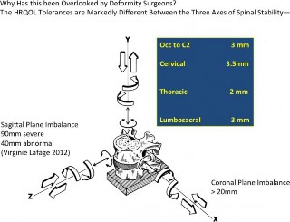
Figure 1. Panjabi’s description of the functional spinal unit. Why has the y- axis, axial spinal height, been overlooked by deformity surgeons? (1) The axial spinal height has to be measured more accurately than sagittal or coronal balance. The Health Related Quality Of Life (HRQOL) negatively correlates with higher thresholds for sagittal balance: sagittal vertical line (SVL) is 48 mm (Lafage et al2) and coronal balance (central sacral vertical line [CSVL]) is 20 mm (Richards et al4) compared to the much smaller axial height critical numbers of
-
-
to 3.5 mm (North American Spine Society white paper10). (2) Instead of straight lines, SVL for sagittal balance (and CSVL for coronal balance), the axial height is ideally a curved line due to cervical lordosis, thoracic kyphosis, and lumbosacral lordosis. (3) Current digital planning software programs exclusively measure straight lines, plumb lines, and angles. The optimal technique quantitating axial height requires a digital software program to measure the pre-, intra-, and postoperative length of a curved line. Measurement of the middle column makes use of the redundancies of the posterior longitudinal ligament (PLL) and vertebral body malalignment; accurate measurement requires visualization of the path of the PLL.
level for reconstructing complex deformities to restore and optimize spinal height on a global level. The importance of coronal balance was realized in the 1980s when Cotrel-Dubousset segmental instru- mentation could cause coronal decompensation (x- axis imbalance).4 In the last decade emphasis has been placed on the health-related quality of life (HRQOL) with sagittal decompensation and the disability that results from flat back syndrome (z- axis imbalance). But what about Panjabi’s third axis, the y axis, which equals spinal axial height (Figure 1)? Why is it that the optimal spinal height in the cervical, thoracic, and lumbosacral spine has remained elusive to deformity surgeons (y-axis optimization)? The other way of posing the question is ‘‘Why does Dubousset’s ‘cone of economy’ not have an optimal height for each individual patient?’’
Measurement Technique and Definition
Middle-Column Gap Balancing
Knee ligament gap balancing has proved to be a highly reproducible and predictive technique in
preoperative planning to calculate the optimal prosthesis height in total knee reconstruction. Gap balancing, a concept originally developed in total knee replacement surgery, optimizes the thickness of the components throughout the entire flexion- extension cycle of the knee joint (120-degree arc of rotation). Total knee reconstruction surgeons have found it useful to tension the medial and lateral collateral ligaments while planning the (distal femoral and proximal tibial) osteotomy cuts in full extension and again in 90 degrees of flexion. This serves to keep the rotational alignment of the femur and tibia in correct anatomical position throughout the 120 degrees of the knee joint’s flexion-extension cycle. Gap balancing in knee surgery is used to determine optimal anterior and posterior implant thickness while simultaneously maintaining smooth ligament tension—if the thickness of the posterior spacer is too thin then a flexion gap is present and the knee joint is unstable in 90 degrees of flexion (positive anterior and posterior knee ligament laxity). This is analogous to our objective, which is to optimize the anterior and posterior spacer height within the intervertebral disk by making use of spinal ligament and annular tension. Therefore middle-column gap balancing (MCGB) is a method of ‘‘gap balancing’’ the ligaments of the spine, specifically balancing the tethering function of the posterior longitudinal ligament (PLL) with the bony height of the middle column. If a middle-column mismatch (MCM) occurs, then a spacer must incorporate this height for the spine to be stable and optimize neuroforaminal height. This method is effective in one or multiple vertebral segments in the cervical, thoracic, and lumbar spine.5,6
Unlike the knee joint, which needs to have a balance in length of the medial and collateral ligaments throughout 120 degrees of flexion-exten- sion, in the spine we need the PLL to act as a tether and only need to get 10 to 20 degrees of motion. The key reason for balance between axial height in the spine is to restore the optimum environment for neurological recovery, specifically at each level, normalization of neuroforaminal height. The neuroforamen is immediately posteriorly adjacent to the middle column; in fact, the anterior border of the neuroforamen is the posterior one-third of the vertebral body and posterior one-third of the intervertebral disk—therefore one would expect its height to be most directly related to the neuro-
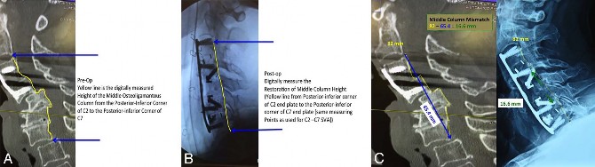
Figure 2. Radiographic illustrations of restoring the middle-column height in an 80-year old-woman with a complex C4-C5 and C5-C6 fracture subluxation with retropulsion of the C5 vertebral body causing Asia B paralysis. (A) Preoperative radiograph showing the measurement of the middle column illustrated as a yellow line (82 mm). (B) Postoperative radiograph after realigning the spine following C5 corpectomy, partial C6 corpectomy, and spacer insertion. The corresponding postoperative measurement of the middle column is shown as a yellow line (also 82 mm). (C) There was severe enough ligamentous disruption that the normal ligamentous tension could not be utilized to gauge correct height restoration using intraoperative distraction-type instruments (no endpoint was reached). Therefore the middle-column measurement on intraoperative radiographs was used to achieve the correct height of the reconstructed spacers. The preoperative and postoperative posterior longitudinal ligament length is shown in yellow as 82 mm. The direct straight-line measurement from the same endpoints is shown in blue as 65.4 mm. The difference between the 2, referred to as the middle-column mismatch, is shown in green: 82 mm 65.4 mm ¼ 16.6 mm. This means that the combined height of the middle column spacers inserted at surgery should total 16.6 mm from C2 to C7. The cervical sagittal vertical line and coronal balance was also restored.
foraminal height compared to the 2 other longitu- dinal spinal columns (anterior or posterior).
Examples of gap balancing in the spine can be found in utility instruments commonly used intraoperatively for spinal reconstruction. They can be used for gap balancing of the spine provided they apply longitudinal tension to deter- mine the optimal length of the PLL without constraining axial rotation or flexion-extension. The problem is that the tendency of surgeons is to apply pure distraction and to flatten out the cervical lordosis, thoracic kyphosis, or lumbar lordosis with these pure distraction devices. These tensioning instruments also simultaneously can correct an alignment offset—they are used to reduce an anterior, posterior, or lateral subluxation in the cervical spine, fracture-dislocation in the thoracic spine, or spondylolisthesis in the lumbar spine. Examples of MCGB instruments include the following:
-
Cloward distractors in the cervical spine
-
Caspar distractors in the cervical spine
-
lamina spreader in the lumbar spine
-
David annular spreader in the lumbar spine7
-
Pinto turnbuckle distractor8
-
Harrington outrigger
-
vertebral column manipulator
-
-
Figure 2A through C show a C4-C5 and C5-C6 fracture dislocation. The preoperative picture is on the left and the postoperative radiograph appears
on the right of Figure 2C. The MCGB is a reference measurement of the path of the PLL, which is reconstructed under tension and balanced by the combined height of the posterior one-third of the vertebral bodies and the posterior one-third of the disks and/or load-sharing spacers. The height restoration of the middle osteoligamentous column and/or PLL is shown by the yellow line measuring 82 mm. The direct boney load-bearing height (top to bottom of blue arrow, 65.4 mm) is the shortest straight line distance between the 2 arrows as the crow flies. The actual middle column or PLL height is a digital measurement of a circuitous line along the topographic contour of the middle column or PLL (yellow line measured at 82 mm) and should be the same measurement both preoperatively and postoperatively if the surgery is performed correctly. Following C5 corpectomy and realigning the cervical spine intraoperatively it is difficult to gauge the correct height of the middle column as the ligaments and soft tissues are disrupted. Therefore one can utilize the middle column measurement on intraoperative radiographs to achieve the correct height of the reconstructed spacers—the middle- column mismatch (MCM) is shown in green—82 mm minus 65.4 mm equals 16.6 mm. Therefore the combined height of the middle-column spacers inserted at surgery should total 16.6 mm from C2 to C7. The cervical sagittal vertical line (SVL) and coronal balance should also be restored.
MATERIALS AND METHODS
Phase 1 Measurement Testing
Determination of Optimal Column for Reliable Measurement of Axial Spinal Global Height— Anterior, Middle or Posterior
Twenty-four consecutive patients who had been enrolled in a prospective randomized trial were evaluated ad hoc due to the fact that they had undergone reliable flexion, extension, and neutral lateral radiographic studies with a calibrated radi- opaque marker. The flexion and extension radio- graphs were reliable in that these radiographs have already been taken as part of a US Food and Drug Administration prospective randomized study, validated by a contract research organization and an independent core radiographic laboratory, Medical Metrics (Houston, Texas). The anterior, middle, and posterior columns were measured using a custom software program capable of measuring the length of curved lines specifically written for this purpose by one of the authors (E.D.), called SpineAlign. This is part of an internet-based program called SketchandCalc. This has been incorporated into a US Food and Drug Adminis- tration–approved commercially available software machine-learning type software (n 1600 patients) called Adaptive Spine Intelligence (Medicrea, New York, New York). The middle-column length was measured using the MCGB technique described above from C3 to C7. The posterior column was measured utilizing reference points delineated as the tips of the spinous processes from C3 to C7. The anterior column length was measured from the anterior border of the C3 vertebral body cephalad corner above to the caudal corner of C7 below along the curved line of the anterior column (the contour of the anterior longitudinal ligament).
Phase 2 Measurement Testing
A different group of 22 consecutive patients undergoing surgery with multilevel deformities for cervical, thoracic, and lumbar procedures had MCGB height measured pre- and postoperatively by 3 blinded observers. The location of the deformities and surgery were distributed as follows (some overlap): cervical (n 6), thoracic (n 5), lumbar (n 15), and sacral (n 6). These measure- ments were performed using neutral lateral images pre- and postoperatively. The preoperative and postoperative measurements were compared using
a linear regression analysis and Pearson product- moment correlation.
Supplemental Case 1
An illustrative case is shown with a full 13-page pdf that methodically goes through each step of the middle-column method in calculating the optimal lumbar interbody patient-specific implant at L2-L3 (Supplemental Material; http://www.ijssurgery.com/ lookup/suppl/doi:10.14444/5024/-/DC1/Supple mentalCase1.pdf).
This is a 50-year-old nurse who was unable to work due to L2-L3 disk collapse. She presented with right thigh numbness and tingling, right hip and right thigh radicular pain in the right L3 nerve root distribution. She also demonstrated grade 4/5 right quadriceps weakness. She failed epidural spinal injections, physical therapy, and conservative measures. The plan was to design and plan the optimal- size spacer following decompression through a posterior laminectomy transforaminal lumbar in- terbody fusion (TLIF) surgical approach.
These are the 4 steps in measurement and planning for patient-specific cage implants:
-
Middle-column linear mismatch: Determine unique height of interdiskal/corpectomy spacers, load-sharing implants.
-
Determine angulation (lordosis-kyphosis): unique sagittal balance via pelvic incidence- lumbar lordosis (PI-LL) angular mismatch.
-
Single-use custom patient-specific instruments trials: Need to measure fit intraop- eratively via intraoperative radiograph and/ or robotically using navigation.
-
Insert the custom patient-specific spacer.
RESULTS
Phase 1
The flexion, extension, and neutral bending radiographs of spinal segments not containing deformities showed that the middle column (C3 to C7) had the most reliable measurements of spinal axial height both in both the actual measurements of change from flexion to extension (mm) and in percentage of change. The actual change from flexion to extension of axial height of each longitudinal spinal column was as follows: anterior column, 7.16 mm; middle column, 4.56 mm; and posterior column, 21.5 mm. The percentage of
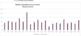
Figure 3. A bar graph illustrates the preoperative and postoperative measurement of the middle column using a proprietary digital mapping program capable of measuring the length of a curved line (SpineAlign). Phase 2 measurement testing of 21 consecutive patients (case 4: 2 measurements, n ¼ 22) undergoing surgery with multilevel deformities for cervical, thoracic, and lumbar procedures had middle-column gap balancing height pre- and postoperatively measured by 3 blinded observers.
change in axial height from C3 to C7 throughout the flexion-extension cycle showed the same relationship (mean, SD): anterior column, 8.74% (SD 4.98%) change; middle column, 6.36% (SD 5.83%) difference; and posterior column, 31.8% (SD 12.2%) change.
In summary, for phase 1 testing, the effect of flexion and extension on the MCGB measurement was found to be more reliable than measurement of spinal height utilizing either the anterior or posterior column. This makes intuitive sense as the middle column is the spinal column that is in closest proximity to the center of rotation for each spinal segment. Therefore in phase 2 testing of deformities, the MCGB was utilized instead of measuring anterior or posterior columns. To minimize error, the radiographs were performed standing and in neutral position (ie, in Dubousset’s cone of econo- my position).
Phase 2
A paired t test was run on a sample of 21 patients (case 4: 2 measurements, n 22) to determine whether there was statistical significance between preoperative and postoperative measurements of the middle osteoligamentous column (Figure 3). In- creases in MCGB length following surgery were negligible (postop: 9.9 6 3.7 cm; preop: 9.8 6 3.4 cm); no statistical difference was found between column lengths (95% confidence interval, 0.42 to 0.17 cm).
A Pearson product-moment correlation was run between each individual’s preoperative and postoperative middle osteoligamentous column measure- ments. There was a strong, positive correlation between preoperative and postoperative measure-
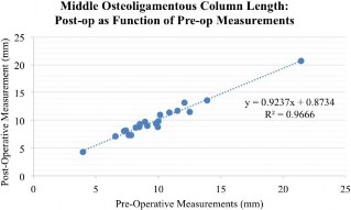
Figure 4. A Pearson product-moment correlation was run between each individual’s preoperative and postoperative middle osteoligamentous column measurements. In total this was a consecutive series of 21 patients (case 4: 2 measurements, , n ¼ 22) presenting with spinal deformities. There was a strong, positive correlation between preoperative and postoperative measurements, which was statistically significant (r ¼ 0.983, n ¼ 21, P , .01) (R2 ¼ 0.9666).
The linear regression line expressed by the formula y 0.9237x 0.8734 is illustrated in Figure
4. There was a high correlation between the preoperative MCGB measurement and the postop- erative reconstructed middle-column height includ- ing spacers, R2 .9666.
The intraobserver and interobserver coefficients of reliability for measurements were R 0.987 and R 0.970, respectively, indicating a very high precision and reliability with regard to the intra- and interobserver measurement results (P , .01). The average percentage of error across all observa- tions for 3 observers was 2.09% (SD 2.62), with no statistical differences detected between observers (P . .05).
Note that this correlation was maintained re- gardless of the vertebral level of deformity: Figure 5A and B illustrate the middle-column height from the occiput to C3 before and after skeletal traction to reduce basilar invagination. Ranawat’s line as a cephalad measure of the middle-column height was used to determine the correct height of lateral mass spacers between the C1 and C2 facet joints. Figure 6A and 4B illustrates the middle-column measure- ments before and after spacer insertion at L5-S1 in reconstruction of a grade II L5-S1 isthmic spondy- lolisthesis.
Supplemental Case 2
A second supplemental case is shown in a 17-page pdf to illustrate the application of a custom 3- dimensional (3-D) printed anterior lumbar inter-
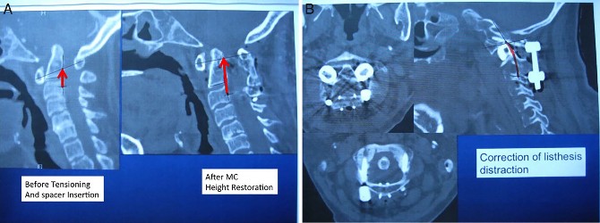
Figure 5. Basilar invagination from rheumatoid arthritis. (A) Ranawat’s line if measured along the posterior longitudinal ligament instead of from the C2 pedicle is actually a measure of middle-column length. The red lines on the pre- and postreduction images are the length of the middle column. For consistency the distances are measured form the midportion of the C3 pedicle to the longest anteroposterior diameter of C1. Ranawat’s line is the same vertical measurement, just starting from the middle of the C2 pedicle—the problem being that this is a negative number preoperatively. Our proposed site of measurement is shown before and after skeletal tong traction and reduction of 7 mm. The starting point is actually not important as long as it is consistently measured along the middle column. The starting point was determined by overlying the midportion of the C3 pedicle from the computed tomography axial image. (B) This corresponds to 7 mm of bilateral spacer reconstruction as titanium spacers were placed between the C1 and C2 lateral masses with restoration of ambulation and neurologic function.
body fusion cage (Supplemental Material; http:// www.ijssurgery.com/lookup/suppl/doi:10.14444/ 5024/-/DC1/SupplementalCase2.pdf). This was a 23-year-old woman with a grade II L5-S1 dysplastic spondylolisthesis who presented with severe L5 ra- diculopathy, neurogenic claudication walking 1 block, and symptoms of spinal cord tethering. She had already undergone failed revision of total hip replacement for hip dysplasia so there was increased importance of having a custom press-fit spine implant be successful with the first spinal procedure.
One of the keys is to obtain good quality imaging studies with a calibration marker in place to allow precise dimensional measurement on flexion radio- graphs (for optimal maximal PLL length), extension radiographs (for optimal anterior longitudinal liga- ment length), magnetic resonance imaging (MRI) in neutral to gauge the optimal final reduction height of the neural elements (middle column), and a 3-D
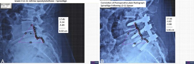
Figure 6. Grade II L5-S1 isthmic spondylolisthesis. (A) The preoperative height of the ligamentous portion of the middle column (posterior longitudinal ligament) was measured utilizing Spine Align, a digital software program capable of measuring a curved perimeter. The 2 extraneous portions of the closed perimeter were subtracted leaving a preoperative middle column length of 60.2 mm, measured from midpedicle of L4 to the midpedicle of S1. (B) Following posterior decompression, pedicle screw L4 to S1 instrumentation and adjustable expandable L5-S1 spacer, the middle-column height was restored to 59.6 mm, or within our acceptable target of
0.6 mm. So, postoperatively using a closed perimeter measurement, the perimeter was 17.66 cm. Therefore, if the extraneous 2 legs of the perimeter measuring 5.82 and 5.88 cm respectively are subtracted out, the curved line of the middle column is 17.66 cm 5.82 cm 5.88 cm ¼ 5.96 cm. In summary, by using a spacer at L5- S1 and reducing the L5-S1 spondylolisthesis the surgery has not overstretched the middle column: preoperative measurement ¼ 6.02 cm and postoperatively the middle column was 5.96 cm. It is hoped that even more exacting postoperative height restoration is possible with precise intraoperative digital measuring techniques.
Figure 7. An extreme case of spinal shortening and the importance of maintenance of preservation of middle column height is shown in this 38-year- old man with a traumatic L3-L4 fracture-dislocation.
CT for optimal fit of the axial cage footprint matching the vertebral endplates.
Another concept that takes advantage of each case is ‘‘adaptive spine intelligence,’’ which allows each additional case using this middle-column measurement system to utilize big data, deep machine learning, and predictive analytics as the trial implants are being modeled. Each dimension can be compared to a large database of prior cases with similar diagnosis and similar vertebral level, and this can be compared to the published literature. This optimizes and serves as a check on the fit of the final manufactured product, which allows less inventory and reduces the need for improvising during the final surgical implantation.
DISCUSSION
The extremes of axial instability deformity are shown by 2 radiographs of thoracolumbar traumat-
Figure 8. The opposite extreme of axial spinal height is shown with another patient with iatrogenic overdistraction at L1 to L2 due to insertion of nonsegmental spinal instrumentation. The measurement of axial height (y- axis) correlates well with the neurologic level of function but it requires more precise measurement (an order of magnitude) compared to imbalances in the coronal and sagittal planes. This is due to the close proximity of the middle column to the neuroforamen (directly adjacent).
ic deformity: extreme compression and extreme distraction. One patient had complete anterior translation and displacement of L2 anterior to L3 (Figure 7). The second case was operated upon with Harrington rods and was grossly overdistracted (Figure 8). This shows the shortcomings of the methodology in having to perform deformity angular measures without the benefit of standing radiographic studies: the axial height or vertical spinal stability needs to be predicted. These extreme cases, one grossly underdistracted and one grossly
overdistracted, highlight the message that spinal height is of critical importance to maintain neuro- logic integrity. In these 2 extreme cases the SVL and CSVL are not markedly abnormal. One can’t know for sure because the plumb lines of global sagittal and coronal alignment are, by convention, per- formed on standing radiographs. MCGB, in contrast, is measured on software utilizing measurement of a curved line and does not have to be performed on weight-bearing radiographs. It is most accurate when correlated with MRI imaging where the PLL can be directly visualized in neutral position.
In the growing spine the most common measure- ment method of the axial height of the spine was reported by Spurway et al.9 The measurement is based on the sagittal spinal length measurement along the midportion of the vertebral bodies. This method is accurate in immature individuals but does not change based on lateral, anterior, or posterior spondylolisthesis. The measurement, unlike the MCGB, is not sensitive to ligamentous instability and therefore not accurate in trauma, degenerative, or adult instability conditions. Our measurement of MCGB is consistent with the definition of instability outlined in the 119-page white paper written by the North American Spine Society10 and the report by Davis et al11 regarding the findings of Orthokinematics based on video motion analysis. If the MCM exceeds 3 mm then middle-column instability leads to surgical stabilization decisions consistent with these 2 major reports.
There are 3 reasons why this critical predictive measurement (MCGB) has been neglected com- pared to sagittal balance angles of the International Spine Study Group: (1) The axial spinal height has to be measured more accurately than sagittal or coronal balance. The HRQOL threshold for sagittal balance SVL is 48 mm and coronal balance (CSVL) is 20 mm compared to axial height critical numbers of 3.0 to 3.5 mm. (2) Instead of straight lines used by SVL for sagittal balance and CSVL for coronal balance, the axial height is ideally a curved line due to cervical and lumbar lordosis or thoracic kypho- sis. Therefore the optimal technique requires a digital software program to measure the pre, intra, and postoperative lengths of a curved line.
(3) Measurement of the middle column makes use of the redundancies of the PLL and vertebral body malalignment; therefore accurate measurement re- quires visualization of the path of the PLL. Usually
this requires MRI to supplement the imaging whereas sagittal and coronal balance can be measured on plain 1-m standing radiographs.
Before the ‘‘middle-column–preserved PLL height’’ concept, commercially available measure- ment tools were not reliable due to the variability of cage position (distance from the PLL to the back wall of the cage), variability of vertebral end plate contours (fish-mouth disk space), and the amount of cage subsidence into the vertebral end plates. The concepts proposed in this article were validated by a publication that came out after this manuscript was submitted. Anand et al12 reported 66 consecutive patients who underwent extreme lateral interbody fusion. They found exactly what our model predict- ed, that the angular correction in the sagittal plane did not directly correlate with the angle of the cage. A major determinant was where the anterior lordotic cage was placed within the disk space relative to the PLL. Think of the PLL as a fixed tether and the farther anterior the lordotic cage is placed, the more likely a taller cage height can be inserted, resulting in more correction. Cages that were the same angulation placed in the anterior, middle, and posterior one-third of the disk space produced 13.02, 11.47, and 8.23 degrees of lordosis, respectively (P , .05).
Additionally, the primary shortcoming of histor- ical computer planning tools is that they could not take into account the degree of spinal instability or subluxation by deriving measurements solely from 1 standing lateral and 1 standing anteroposterior radiograph. Instead the ligamentous instability and change in angulation from flexion and extension standing radiographs, CT and MRI measurements of the middle-column length/redundancy needed to be incorporated. Figure 9 shows 2 MRI mismatches that were calculated from 2 different patients: the patient on the left had an isthmic spondylolisthesis (MCM 11.5 mm); the patient on the right had a dysplastic spondylolisthesis (MCM 0). The amount of slippage or L5-S1 translation was equivalent on their 2 respective standing lateral radiographs at L5-S1. However, the spinal recon- struction for the patient on the left should incorporate a spacer measuring 11.5 mm in height. In contrast, the patient with dysplastic spondylolis- thesis and a MCM 0 is tethered by the nerve roots, filum terminale, and PLL. Any increase in spinal height could lead to axial stretching as there is no redundancy in the spinal soft tissues.
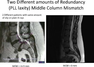
Figure 9. The sagittal magnetic resonance images are shown from 2 different patients, each with approximately the same degree of slippage or L5-S1 translation from spondylolisthesis apparent on their respective plain radiographs. The amount of middle-column mismatch (MCM) was calculated for each: the patient on the left had an isthmic spondylolisthesis (MCM ¼ 11.5 mm), whereas the patient on the right had a dysplastic spondylolisthesis (MCM ¼ 0). However, the spinal reconstruction for the patient on the left should incorporate a spacer measuring 11.5 mm in height. In contrast, the patient with dysplastic spondylolisthesis and a MCM ¼ 0 is tethered by the nerve roots, filum terminale, and posterior longitudinal ligament. Any increase in spinal height could lead to axial stretching as there is no redundancy in the spine. Correction of the spondylolisthesis in this case should incorporate a neutral height cage equal to the amount of middle column resection in the decompressive part of the operation.
Correction of the spondylolisthesis in this case must incorporate a neutral-height cage equal to the amount of middle-column resection in the decompressive part of the operation.
The concepts in this manuscript gave rise to a custom-designed program, which is commercially available, called Adaptive Spine Intelligence. It utilizes the PLL in predicting the optimal postoperative middle column height as part of a commercially available iterative virtuous cycle. The overall approach uses machine learning on a large database of over 1600 deformity procedures that has helped reduce the incidence of rod breakage at 1 year follow-up from 14.9% down to only 2.2% (Figure 10). The software programs and data provide commercially available planning for complex deformity to optimize the PI-LL angular mismatch and also optimize the linear MCM (PLL boney height of middle column) toward optimal postoperative spinal balance.
The second illustrative case study shows that current applications of the MCM can be used to optimize custom 3-D printed cages. Obviously the larger surface area of cage, the less subsidence would result postoperatively, which is why direct lateral interbody fusion, xtreme lateral interbody fusion, and lateral lumbar interbody fusion would
be expected to have less subsidence than TLIF. The limitation in the sagittal correction of height is the PLL; however, the limitation of correction of sagittal balance using the effective height of the PLL with a hyperlordotic cage is the anterior longitudinal ligament release. The iterative software allows multiple combinations of sagittal angular corrections and posterior cage wall heights to be simulated. Each simulation builds on the database of over 1600 historical cases. The second illustrative case demonstrates the MCM of 0, which means the custom 3-D printed cage has to be incorporated without distracting the PLL and the nerve roots. In the prospective series of cases currently underway we have been able to correct 25 to 30 degrees of sagittal imbalance at one level without overstretching the PLL as long as the anterior longitudinal ligament is released. This is most easily accomplished at L5-S1. This case illustrates what is commercially available now with an iterative preoperative planning process with various simula- tions to optimize cage angulation and height—with no elongation of the PLL due to nerve root tethering. Slide 7 has a plan with a 31-degree lordotic cage; Slide 5 shows a 13-degree lordotic cage. The final compromise was a 3-D printed spacer (Slide 15) inserted (Slide 16)—25-degree lordosis with the exact cross-sectional footprint matching the S1 vertebral end plate to prevent subsidence.
At the 50th anniversary meeting of the Scoliosis Research Society, Ames et al,13,14 reporting for the Cervical International Spine Study Group stated that their complications of C8 radiculopathy were over 10% in cervicothoracic osteotomies. As a technique to reduce this complication, Ames et al reported that they were changing the site of the cervicothoracic osteotomies down to T2-T3. In- stead, we have found that the osteotomies can still be safely performed at C7-T1 provided an anterior spacer is inserted anteriorly at C7-T1 to maintain the middle-column height immediately after obtain- ing the angular correction. Rather than changing the location of cervical osteotomies due to higher than desired neurological adverse events, the height of the middle column can be safely reconstructed during a second stage of the posterior osteotomy procedure.
At this time historical digital mapping software techniques are not measuring the middle-column length. They attempt to realign the spine essentially
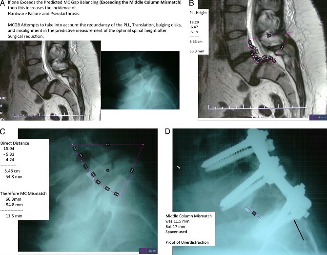
Figure 10. Overdistraction of the middle column. This is a patient from Elsewhere General not included in this deformity series but she presented during the time course of this study. (A) This 40-year-old woman presented with neurogenic claudication from a grade II L5-S1 isthmic spondyloisthesis. (B) The preoperative magnetic resonance image shows the length of the posterior longitudinal ligament from the midpedicle of L4 to the midpedicle of S1 ¼ 66.3 mm. (C) The bony load- bearing components of the middle column measures 54.8 mm utilizing the same endpoints. Therefore the middle-column mismatch (MCM) ¼ 66.3 mm 54.8mm ¼ 11.5 mm. (D) Unfortunately, an interbody spacer and reduction had been done elsewhere. In retrospect the spine had been overdistracted with a 17-mm-high spacer exceeding the optimal 11.5 mm MCM. She presented to us with persistent L5 radiculopathy and a broken S1 screw due to overdistraction at the time of the original surgery. A higher incidence of radiculopathy, neuropraxia, pseudarthrosis, and instrumentation failure would be expected if the optimal predictions of MCM are exceeded.
by cutting up JPEG images based on a single standing radiograph. This can lead to a good conceptual understanding of the possible outcomes of sagittal imbalance correction. However, the inadvertent lengthening and shorting of the anterior and posterior spinal columns is not quantitated or appreciated. This is of obvious importance as the height of the middle column and neuroforamen must be preserved to ensure an optimal environment for neurologic recovery. The techniques and assumptions of historical digital software mapping programs are illustrated in Figure 11A and B. A single sagittal standing radiograph has been re-
aligned in normal sagittal balance by cutting and rotation of 4 images. The default pivot point is the location of the pedicle screw tulips for posterior rod placement. This leads to inadvertent stretching of the middle column and anterior soft tissues. This may or may not be physiologically beneficial. Furthermore, the information from MRI, CT, video motion analysis, etc. regarding ligament and neural tissue tension has not been incorporated into the computer model. If the pivot point is altered to be within the middle column in order to preserve this exact height postoperatively ,the effect of the posterior column is easily seen in the fragmented
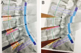
Figure 11. 2 different preoperative planning models are illustrated in commercially available software programs utilizing DICOM images. (A) The default programs essentially cut up a JPEG in horizontal strips and rotate them along a pivot point overlying the eventual position of the posterior spinal rod. The priority of uniformly all current commercially available programs is to correct sagittal imbalance. (B) If the pivot points are moved to an alternate location, such as the middle column, the effect of inadvertent and unanticipated distortion of spinal soft tissue can be appreciated. The information on magnetic resonance imaging, computed tomography, or flexion-extension radiographs are not currently integrated into these measurements. Correct determination of cage or middle-column reconstruction requires consideration of soft tissue tension; the tension of the posterior longitudinal ligament should be considered in order to optimize neuroforaminal height postoperatively. Notice the distortion of the blue rod, which reflects the translation that must also be present in the neural canal to some extent.
image of the posterior rod. One can identify the difference in the 2 techniques by looking at the offset of the 4 images at the blue rod in the Figure
-
Figure 12 is the preoperative and postoperative images digitally manipulated with the pivot point at the posterior rod. This shows that the correction of
angular PI minus LL mismatch can be achieved, but there is inadvertent and unanticipated lengthening of the middle column:111.3 mm 104.1 mm 7.2 mm. The 3 dark triangles at the left side of Figure 12B indicate the areas of soft tissue stretching, which needs to occur intraoperatively in order to achieve the degree of realignment predicted from the digital mapping program.
The historical digital mapping software programs distract the anterior aspect of the spinal canal and stretch the soft tissues (nerves and spinal canal) without even measuring this effect. The goal in the future is to measure the redundancy in the PLL on the MRI to take the native length of the PLL and middle column into account before overdistracting the anterior and middle columns.
Case 10 illustrates a patient referred to us from Elsewhere General more recently than the cases measured in this study. It shows a 40-year-old woman with a grade II isthmic spondylolisthesis at L5-S1 with an MRI demonstrating 66.3 mm of PLL length. The preoperative imaging studies confirmed a 54.8-mm bony direct measurement. The MCM was therefore 66.3 mm 54.8 mm 11.5 mm. Unfortunately, an interbody spacer and reduction had been done elsewhere. In retrospect the spine had been overdistracted with a 17-mm-high spacer exceeding the optimal 11.5-mm MCM. She present- ed to us with persistent L5 radiculopathy and a broken S1 screw due to overdistraction at the time of the original surgery. Radiculopathy, neuropraxia,
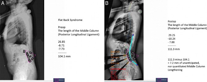
Figure 12. Flat back syndrome. (A) The preoperative middle-column height is 104.1 mm. (B) The postoperative middle-column height utilizing a commercially available digital mapping program measuring the same endpoints is 111.3 mm, indicating 7.2 mm of overdistraction. This may or may not create symptoms but the stretching and alteration of soft tissues, especially neural elements, needs to be appreciated—they are not integrated into the programs. The 3 triangular wedges of missing radiographic data on the lower left half of the image represent unanticipated lengthening of soft tissues.
pseudarthrosis, and instrumentation failure would be expected if the optimal predictions of MCM are exceeded. A prospective multi-institutional trial is currently underway to determine how closely clinical outcome instruments correlate with mid- dle-column axial height balance.
SUMMARY
In phase 1 testing, the effect of flexion and extension on the MCGB measurement was found to be negligible. The height of the middle column was found to be more reliable than measurement of spinal height utilizing either the anterior or posterior columns—this makes intuitive sense as the middle column is the spinal column in closest proximity to the center of rotation for each spinal segment.
The predictive value of pre and postoperative spinal height utilizing MCGB was found to be highly correlated and reproducible with only small inter- and intraobserver errors. In contrast, the assessment of spinal axial height utilizing intervertebral disk height was not significant and not reliable. Digital measuring tools can be unreliable, with a large amount of variability. This is because the ultimate postoperative cage correction (disk height and angulation) are dependent on anterior- posterior cage position, the variability of vertebral end plate contour, and the amount of vertebral endplate subsidence. This is why in our experience a 30-degree hyperlordotic cage may not reliably lead to 30 degree correction of sagittal plane imbalance. The middle-column technique (MCGB) led to predictable postoperative height by taking into account the laxity and tethering effect of the PLL.
REFERENCES
-
Labelle H, Mac-Thiong JM, Roussouly P. Spino-pelvic sagittal balance of spondylolisthesis: a review and classification. Eur Spine J. 2011;20(Suppl 5):641–646.
-
Lafage V, Smith JS, Bess S, et al. Sagittal spino-pelvic alignment failures following three column thoracic osteotomy for adult spinal deformity. Eur Spine J. 2012;21(4):698–704.
-
Schwab F, Ungar B, Blondel B, et al. Scoliosis Research Society–Schwab adult spinal deformity classification: a valida- tion study. Spine (Phila Pa 1976). 2012; 37(12):1077–1082.
-
Richards BS, Birch JG, Herring JA, Johnston CE, Roach JW. Frontal plane and sagittal plane balance following
Cotrel-Dubousset instrumentation for idiopathic scoliosis.
Spine (Phila Pa 1976). 1989 Jul;14(7):733–737.
-
McAfee PC, inventor. Methods and apparatus for spinal reconstructive surgery, measuring spinal length and intervertebral spacing at the middle column, measuring intervertebral tension and establishing intervertebral spacer heights. US patent and trademark application 62250743. November 4, 2015.
-
McAfee PC, Eiserman L, Cunningham BW, Mullinix KA, Brooks DM. Middle column gap balancing to predict optimal anterior structural support and spinal height in spinal reconstructive surgery. Spine (Phila Pa 1976). 2017;42(Suppl 7):S19–S20.
-
David T. Long-term results of one level lumbar arthroplasty: minimum 10 year follow up of the Charite´ artificial disk in 106 patients. Spine (Phila Pa 1976). 2007;32 (6):661–666.
-
Pinto WC, Avanzi O, Winter RB. An anterior distractor for the intraoperative correction of kyphosis. Spine (Phila Pa 1976). 1978;3(4):309–312.
-
Spurway AJ, Chukwunyerenwa CK, Kista WE, Hurry JK, El-Hawary R. Sagittal spinal height measurement: a novel technique to assess the growth of the spine. J Spinal Deformity. 2016;4(5):331–337.
-
North American Spine Society. Evidence-Based Clinical Guidelines for Multidisciplinary Spine Care. Diagnosis and Treatment of Degenerative Spondylolisthesis. Burr Ridge, IL: North American Spine Society. 2014.
-
Davis RJ, Lee DC, Wade C, Cheng B. Measurement performance of a computer assisted vertebral motion analysis system. Int J Spine Surg. 2015;9(36):1–13.
-
Anand N, Cohen RB, Cohen J. The influence of lordotic cages on creating sagittal balance in CMIS treatment of adult spinal deformity. Int J Spine Surg. 2017:11(3):183–192.
-
Ames CP, Smith JS, Eastlack R, et al. Reliability assessment of a novel cervical spine deformity classification system. J Neurosurg Spine. 2015;23(6):673–683.
-
Ames CP. Advanced cervical thoracic deformity assessment and treatment techniques. In: 50th Annual Meeting of the Scoliosis Research Society Program Book. Minneapolis, MN. 2015;128–130.
-
Corresponding Author: Paul C. McAfee, MD, MBA, Towson Orthopaedic Associates, O’Dea Medical Arts Building, Suite 104, 7505 Osler Drive, Towson, MD 21204.